Virtual Sun™
OVERVIEW - INSTALLATION MANUAL
Spec Code:
Enter your spec code above for a shorter manual customized to your fixtures. This full version covers every spec code.
Virtual Sun
Installation Manual
North American Variants
Table of Contents
What's included2
Wiring instructions3
Quick test power cord4
0-10V controls5
DALI-2 DT8 controls7
DMX controls8
Wireless group installation9
Clearance10
Installation instructions11
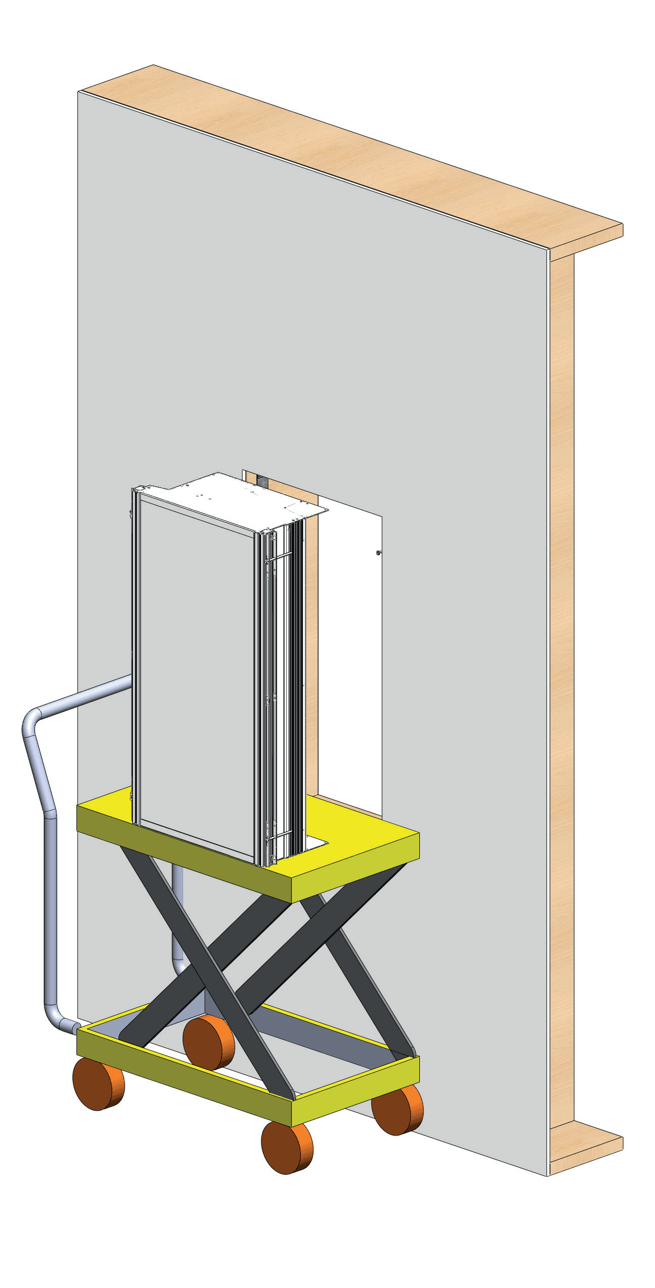
Drywall hoist setup12
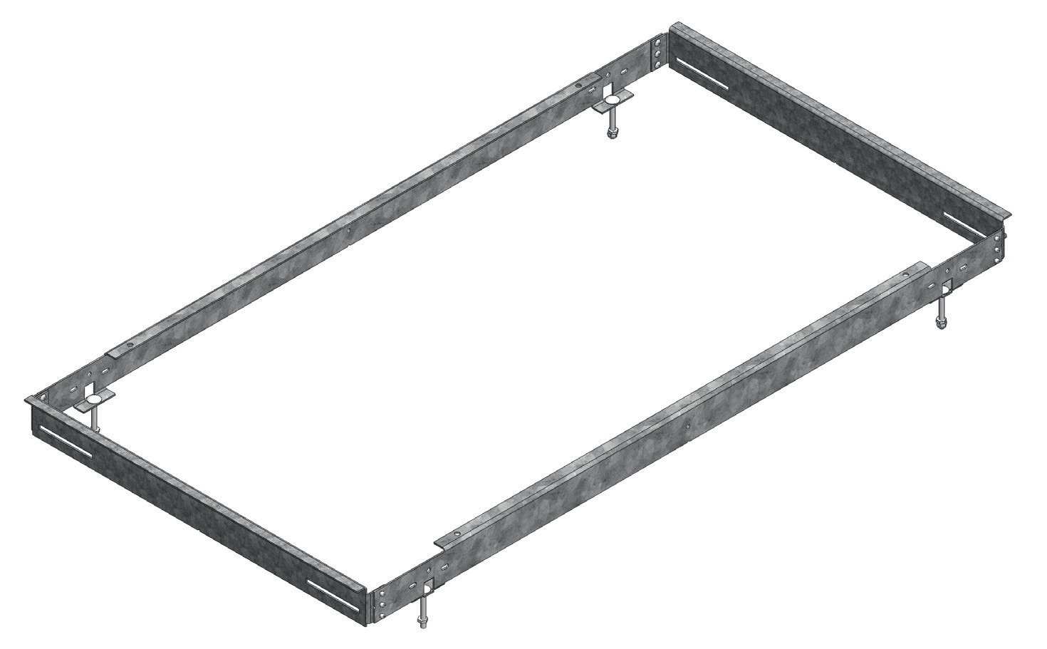
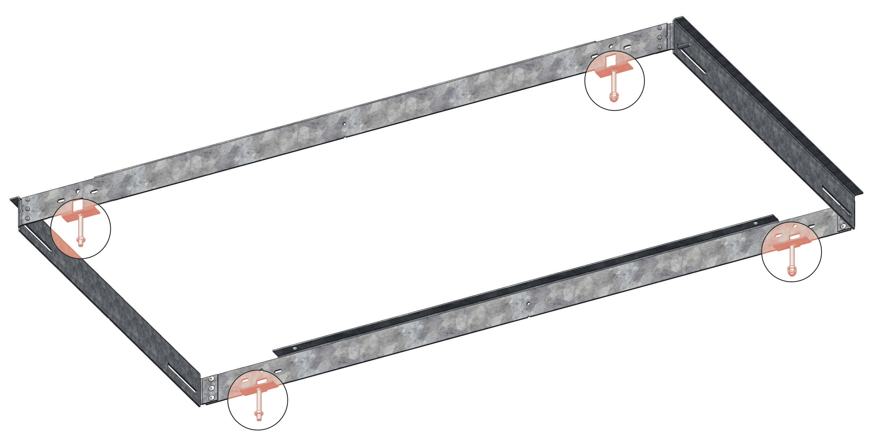
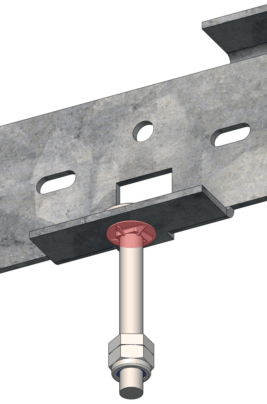
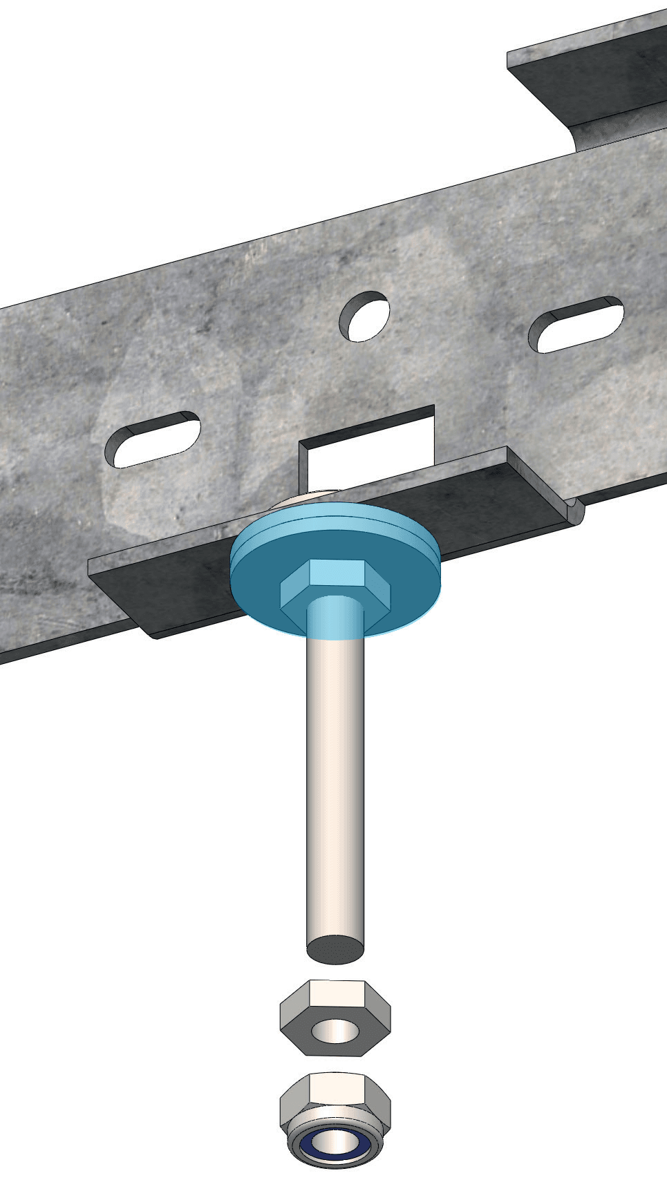
NC Housing prep13
NC Housing — Timber Joists14
NC Housing — Hat Channels / Furring19
NC Housing — Grid Ceilings24
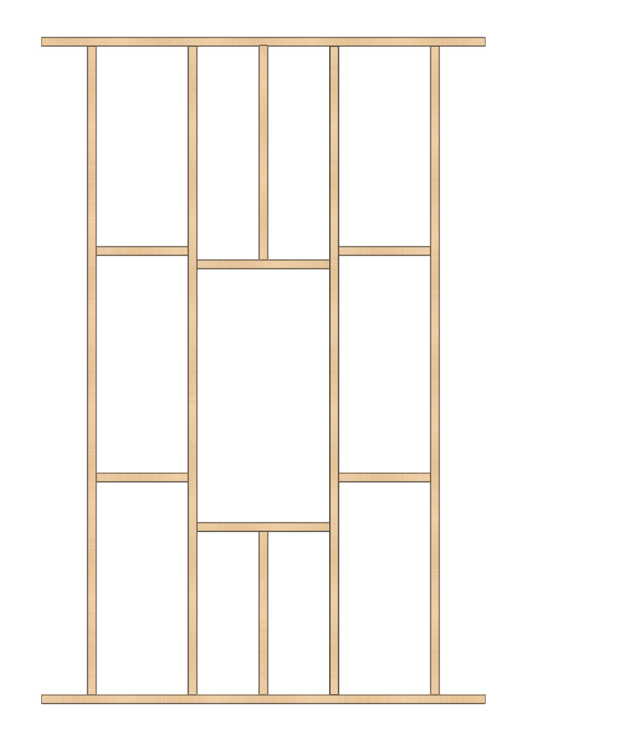
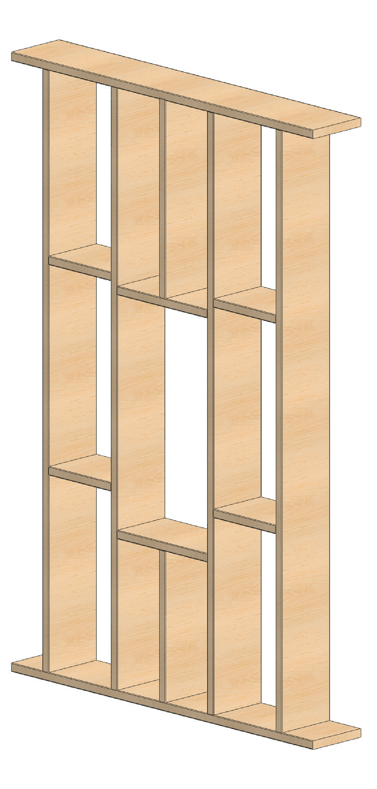
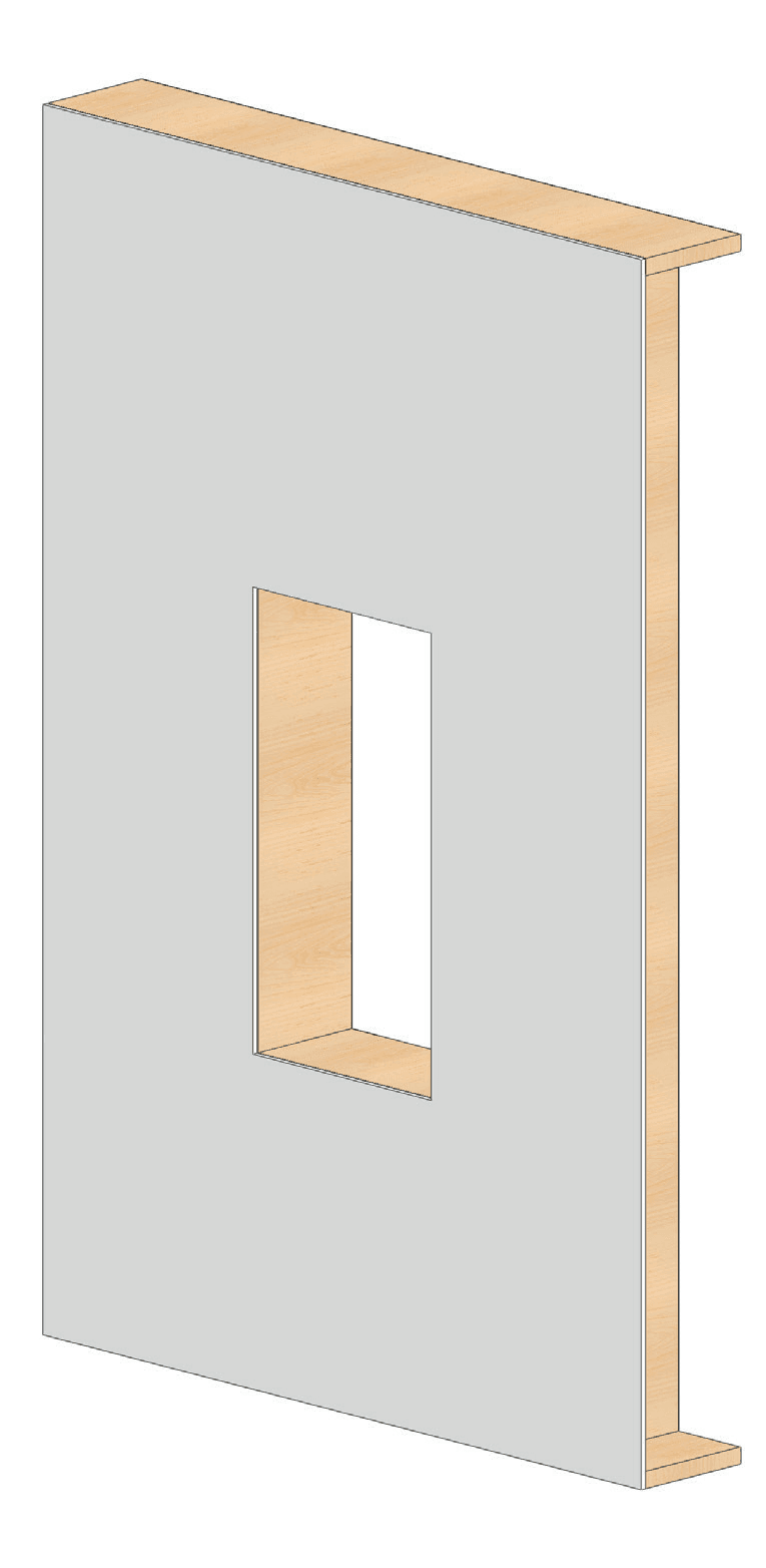
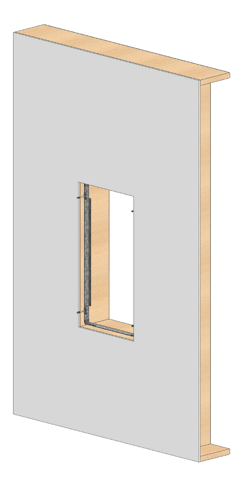
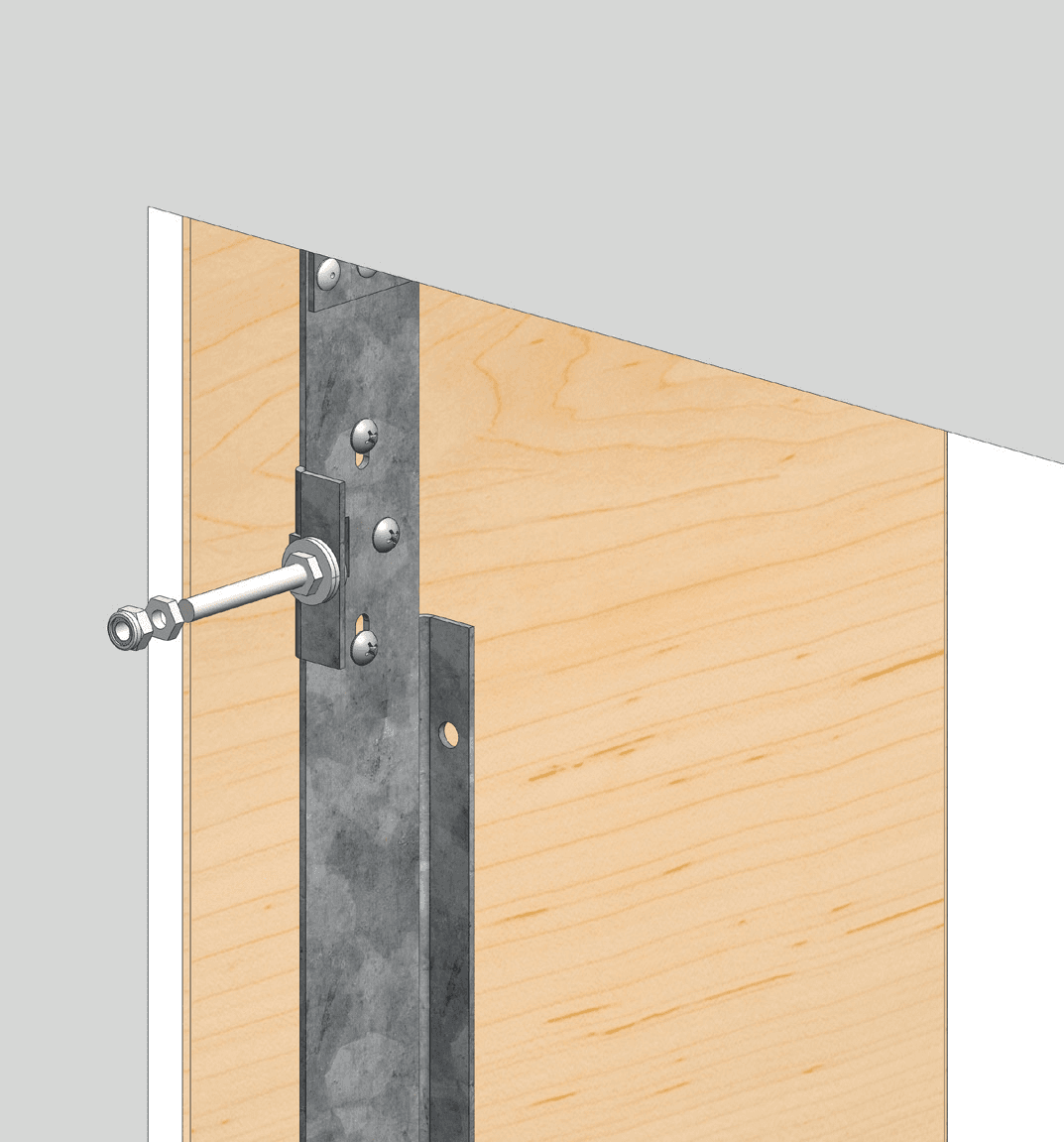
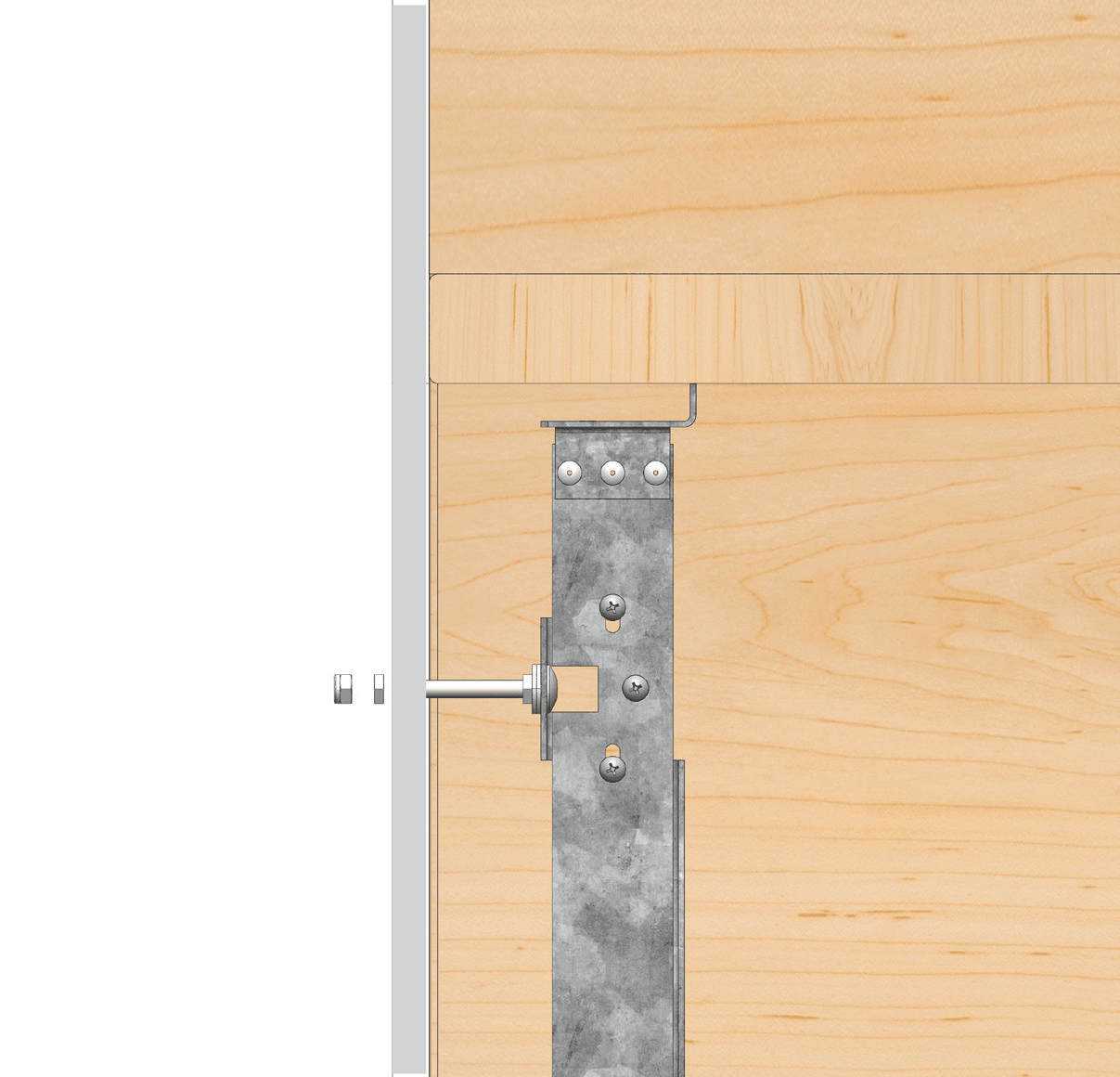
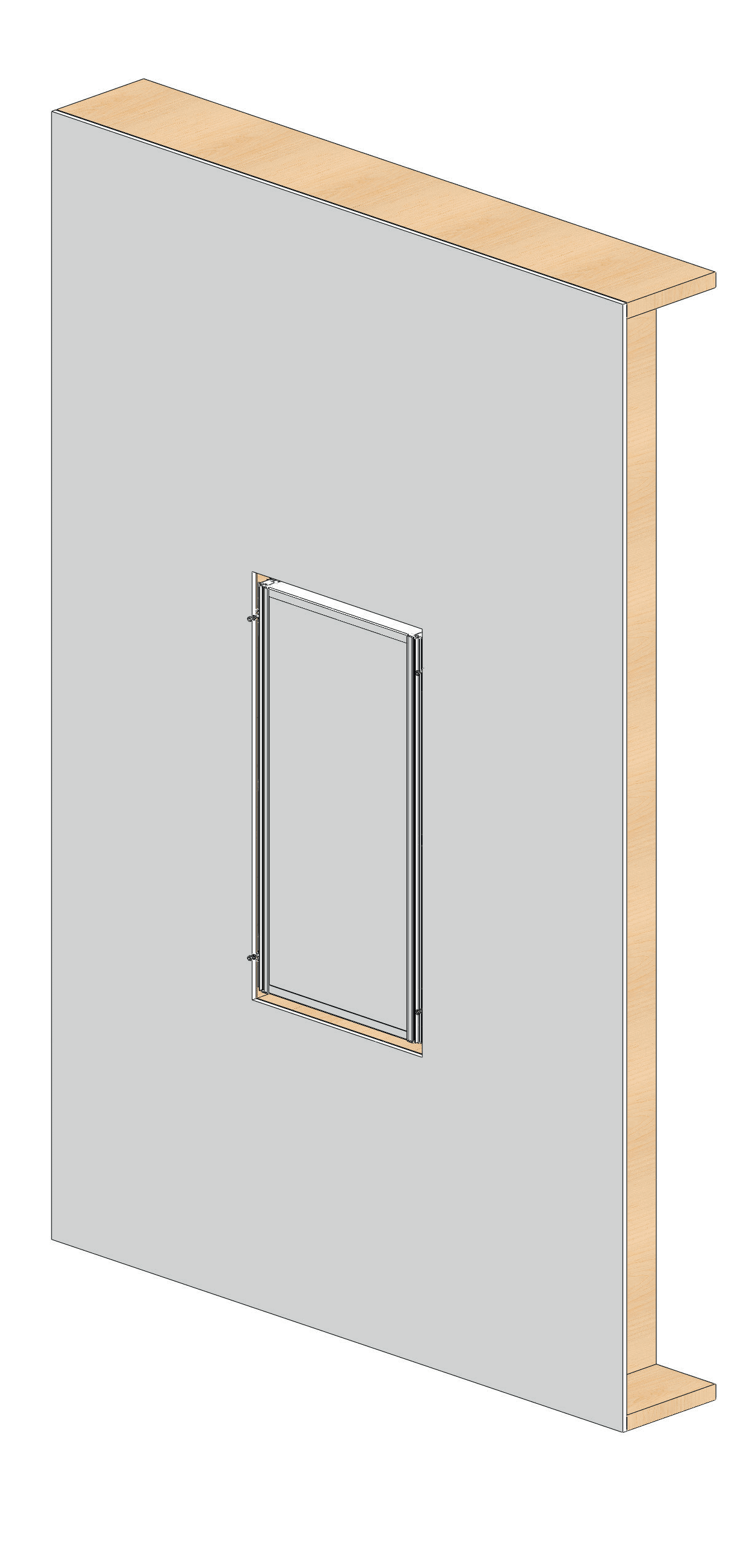
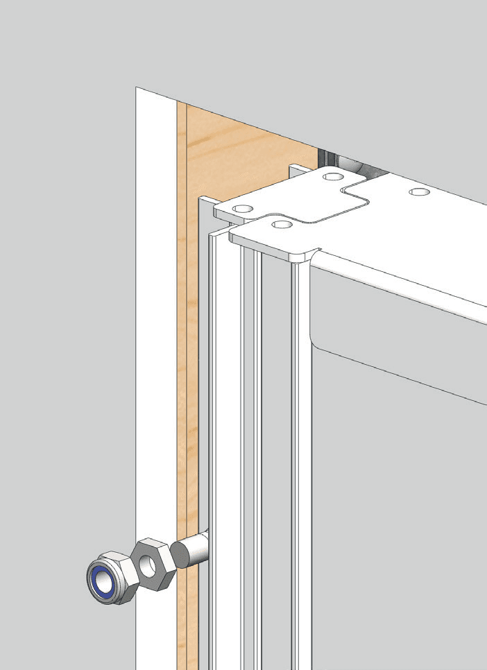
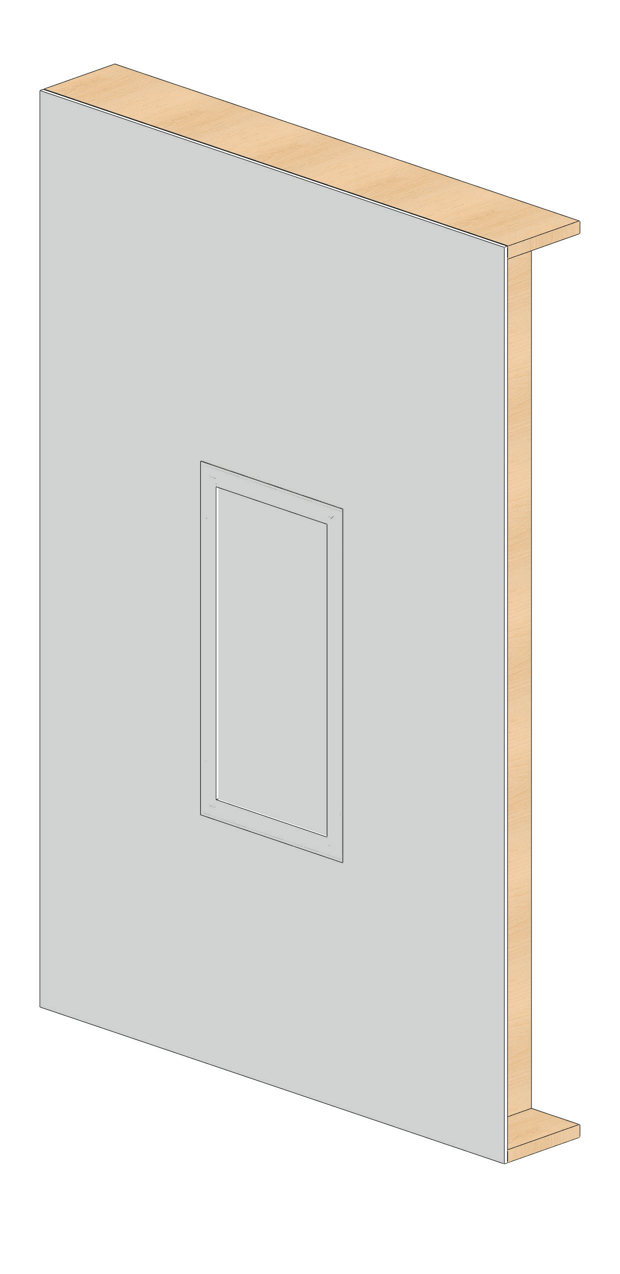
NC Housing — Stud Wall (Wall Mount)34
Cleaning40
Commissioning: Controller & Studio App41